| R902038516 | AXIAL-PISTON MOTOR A2FM16/61W-VBB040-S |
| R902153740 | AXIAL-PISTON MOTOR A2FM16/61W-VBB040-S |
| R902156158 | AXIAL-PISTON MOTOR A2FM16/61W-VBB040-S |
| R902193353 | AXIAL-PISTON MOTOR A2FM16/61W-VBB040 |
| R902193379 | AXIAL-PISTON MOTOR A2FM16/61W-VBB040 |
| R902193591 | AXIAL-PISTON MOTOR A2FM16/61W-VBB040 |
| R902196980 | AXIAL-PISTON MOTOR A2FM16/61W-VBB040 |
| R902197583 | AXIAL-PISTON MOTOR A2FM16/61W-VBB040 |
| R902197624 | AXIAL-PISTON MOTOR A2FM16/61W-VBB040 |
| R902197688 | AXIAL-PISTON MOTOR A2FM16/61W-VBB040 |
| R902197819 | AXIAL-PISTON MOTOR A2FM16/61W-VBB040 |
| R902197868 | AXIAL-PISTON MOTOR A2FM16/61W-VBB040 |
| R902198033 | AXIAL-PISTON MOTOR A2FM16/61W-VBB040 |
| R902201551 | AXIAL-PISTON MOTOR A2FM16/61W-VBB040 |
| R902201559 | AXIAL-PISTON MOTOR A2FM16/61W-VBB040 |
| R902202311 | AXIAL-PISTON MOTOR A2FM16/61W-VBB040 |
| R902215275 | AXIAL-PISTON MOTOR A2FM16/61W-VBB040-S |
| R902217520 | AXIAL-PISTON MOTOR A2FM16/61W-VBB040 |
| R902230015 | AXIAL-PISTON MOTOR A2FM16/61W-VBB040*GO2EU* |
| R902232961 | AXIAL-PISTON MOTOR A2FM16/61W-VBB040-S |
| R902245513 | AXIAL-PISTON MOTOR A2FM16/61W-VBB040 |
| R902245972 | AXIAL-PISTON MOTOR A2FM16/61W-VBB040-S |
| R902255940 | AXIAL-PISTON MOTOR A2FM16/61W-VBB040V-S |
| R902257837 | AXIAL-PISTON MOTOR A2FM16/61W-VBB040 |
| R902261242 | AXIAL-PISTON MOTOR A2FM16/61W-VBB040 |
| R902270520 | AXIAL-PISTON MOTOR A2FM16/61W-VBB040 |
| R902270624 | AXIAL-PISTON MOTOR A2FM16/61W-VBB040V-S |
| R909411120 | AXIAL-PISTON MOTOR A2FM16/61W-VBB040 |
| R909418875 | AXIAL-PISTON MOTOR A2FM16/61W-VBB040-S |
| R909429585 | AXIAL-PISTON MOTOR A2FM16/61W-VBB040 |
| R909448047 | AXIAL-PISTON MOTOR |
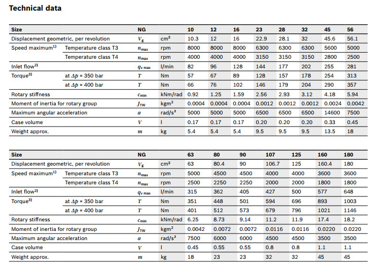
Table of values
| Size | 5 | 10 | 12 | 16 | 23 | 28 | 32 | 107 | 125 | 160 | 180 | 200 | 250 | 355 | 500 | 710 | 1000 | |||
| Displacement | Vg | cm³ | 4.93 | 10.3 | 12 | 16 | 22.9 | 28.1 | 32 | 106.7 | 125 | 160.4 | 180 | 200 | 250 | 355 | 500 | 710 | 1000 | |
| Nominal pressure | pnom | bar | 315 | 400 | 400 | 400 | 400 | 400 | 400 | 400 | 400 | 400 | 400 | 400 | 350 | 350 | 350 | 350 | 350 | |
| Maximum pressure | pmax | bar | 350 | 450 | 450 | 450 | 450 | 450 | 450 | 450 | 450 | 450 | 450 | 450 | 400 | 400 | 400 | 400 | 400 | |
| Maximum speed | nnom 1) | rpm | 10000 | 8000 | 8000 | 8000 | 6300 | 6300 | 6300 | 4000 | 4000 | 3600 | 3600 | 2750 | 2700 | 2240 | 2000 | 1600 | 1800 | |
| nmax 2) | rpm | 11000 | 8800 | 8800 | 8800 | 6900 | 6900 | 6900 | 4400 | 4400 | 4000 | 4000 | 3000 | |||||||
| Inlet flow 3) | at nnom | qV | l/min | 49 | 82 | 96 | 128 | 144 | 177 | 202 | 427 | 500 | 577 | 648 | 550 | 675 | 795 | 1000 | 1136 | 1600 |
| Torque 4) | at pnom | M | Nm | 24.7 | 66 | 76 | 102 | 146 | 179 | 204 | 679 | 796 | 1021 | 1146 | 1273 | 1393 | 1978 | 2785 | 3955 | 5570 |
| Rotary stiffness | c | kNm/rad | 0.63 | 0.92 | 1.25 | 1.59 | 2.56 | 2.93 | 3.12 | 11.2 | 11.9 | 17.4 | 18.2 | 57.3 | 73.1 | 96.1 | 144 | 270 | 324 | |
| Moment of inertia for rotary group | JTW | kg·m² | 0.00006 | 0.0004 | 0.0004 | 0.0004 | 0.0012 | 0.0012 | 0.0012 | 0.0116 | 0.0116 | 0.022 | 0.022 | 0.0353 | 0.061 | 0.102 | 0.178 | 0.55 | 0.55 | |
| Maximum angular acceleration | ɑ | rad/s² | 5000 | 5000 | 5000 | 5000 | 6500 | 6500 | 6500 | 4500 | 4500 | 3500 | 3500 | 11000 | 10000 | 8300 | 5500 | 4300 | 4500 | |
| Case volume | V | l | 0.17 | 0.17 | 0.17 | 0.2 | 0.2 | 0.2 | 0.8 | 0.8 | 1.1 | 1.1 | 2.7 | 2.5 | 3.5 | 4.2 | 8 | 8 | ||
| Weight (approx.) | m | kg | 2.5 | 5.4 | 5.4 | 5.4 | 9.5 | 9.5 | 9.5 | 32 | 32 | 45 | 45 | 66 | 73 | 110 | 155 | 325 | 336 | |
| 1) | These values are valid at: - for the optimum viscosity range from vopt = 36 to 16 mm2/s - with hydraulic fluid based on mineral oils |
| 2) | Intermittent maximum speed: overspeed for unload and overhauling processest, t < 5 s and Δp < 150 bar |
| 3) | Restriction of input flow with counterbalance valve |
| 4) | Torque without radial force, with radial force see table "Permissible radial and axial forces of the drive shafts" |
Note
- The values in the table are theoretical values, without consideration of efficiencies and tolerances. The values are rounded.
- Exceeding the maximum or falling below the minimum permissible values can lead to a loss of function, a reduction in operational service life or total destruction of the axial piston unit. Other permissible limit values, such as speed variation, reduced angular acceleration as a function of the frequency and the permissible angular acceleration at start (lower than the maximum angular acceleration) can be CONTACT US.
Speed range
No limit to minimum speed nmin. If uniformity of motion is required, speed nmin must not be less than 50 rpm.
| Determining the operating characteristics | ||
| Inlet flow |
| [l/min] |
| Rotational speed |
| [rpm] |
| Torque |
| [Nm] |
| Power |
| [kW] |


| Key | |
| Vg | Displacement per revolution [cm3] |
| Δp | Differential pressure [bar] |
| n | Rotational speed [rpm] |
| ηv | Volumetric efficiency |
| ηhm | Hydraulic-mechanical efficiency |
| ηt | Total efficiency (ηt = ηv • ηhm) |
Hydraulic fluids
The axial piston unit is designed for operation with mineral oil HLP according to DIN 51524.
Application instructions and requirements for hydraulic fluids should be taken from the following data sheets before the start of project planning:
90220: Hydraulic fluids based on mineral oils and related hydrocarbons
90221: Environmentally acceptable hydraulic fluids
90222: Fire-resistant, water-free hydraulic fluids (HFDR, HFDU)
90223: Fire-resistan, water-containing hydraulic fluids (HFAE, HFAS, HFB, HFC)
90225: Restricted technical data for operation with fire-resistant hydraulic fluids
Viscosity and temperature of hydraulic fluids
|
| Viscosity | Shaft | Temperature1) | Comment |
| Cold start | νmax ≤ 1600 mm²/s | NBR2) | ϑSt ≥ -40 °C | t ≤ 3 min, without load (p ≤ 50 bar), n ≤ 1000 rpm, |
| FKM | ϑSt ≥ -25 °C | |||
| Warm-up phase | ν = 400 … 1600 mm²/s |
| t ≤ 15 min, p ≤ 0.7 • pnom and n ≤ 0.5 • nnom | |
| Continuous operation | ν = 10 … 400 mm²/s3) | NBR2) | ϑ ≤ +78 °C | measured at port T |
| FKM | ϑ ≤ +103 °C | |||
| νopt = 16 … 36 mm²/s | range of optimum operating viscosity and efficiency | |||
| Short-term operation | νmin = 7 … 10 mm²/s | NBR2) | ϑ ≤ +78 °C | t ≤ 3 min, p ≤ 0.3 • pnom measured at port T |
| FKM | ϑ ≤ +103 °C |
| 1) | If the specified temperatures cannot be maintained due to extreme operating parameters, please contact us. |
| 2) | Special version, please contact us. |
| 3) | Equates e.g. with the VG 46 a temperature range of +5 °C to +85 °C (see selection diagram) |
Note
To reduce high temperature of the hydraulic fluid in the axial piston unit we recommend the use of a flushing and boost pressure valve (see chapter Extended functions and versions).
Dependent on the unit size flushing the case at port U can be carried out alternatively.
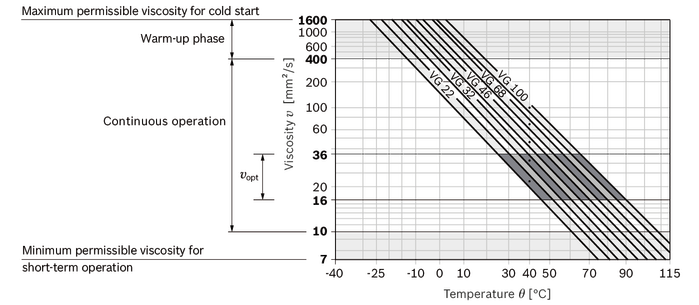
Explanatory note regarding the selection of hydraulic fluid
The hydraulic fluid should be selected such that the operating viscosity in the operating temperature range is within the optimum range (vopt see selection diagram).
Selection diagram
Filtration of the hydraulic fluid
Finer filtration improves the cleanliness level of the hydraulic fluid, which increases the service life of the axial piston unit.
A cleanliness level of at least 20/18/15 is to be maintained according to ISO 4406.
At a hydraulic fluid viscosity of less than 10 mm²/s (e.g. due to high temperatures in short-term operation) at the drain port, a cleanliness level of at least 19/17/14 according to ISO 4406 is required.
For example, the viscosity is 10 mm²/s at:
- HLP 32 a temperature of 73°C
- HLP 46 a temperature of 85°C
Operating pressure range
| Pressure at working port A or B (high-pressure side) | Definition | ||
| Nominal pressure | pnom | see table of values | The nominal pressure corresponds to the maximum design pressure. |
| Maximum pressure | pmax | see table of values | The maximum pressure corresponds to the maximum operating pressure within the single operating period. The sum of the single operating periods must not exceed the total operating period. |
| Single operating period | 10 s | ||
| Total operating period | 300 h | ||
| Minimum pressure | pHP min | 25 bar | Minimum pressure on high-pressure side (port A or B) required to prevent damage to the axial piston unit. |
| Minimum pressure at inlet (pump operating mode) | pE min | see diagram | To prevent damage to the axial piston motor in pump mode (change of high-pressure side with unchanged direction of rotation, e.g. when braking),a minimum pressure must be guaranteed at the working port (inlet). The minimum pressure depends on the rotational speed and displacement of the axial piston unit. |
| Total pressure | pSu | 700 bar | The summation pressure is the sum of the pressures at both work ports (A and B). |
| Rate of pressure change | Definition | ||
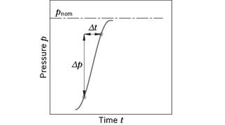
| with integrated pressure relief valve | RA max | 9000 bar/s | Maximum permissible rate of pressure build-up and reduction during a pressure change over the entire pressure range. |
| without pressure relief valve | RA max | 16000 bar/s | |
| Case pressure at port T | Definition | ||
| Continuous differential pressure | ΔpT cont | 2 bar | Maximum averaged differential pressure at the shaft seal (case to ambient) |
| Pressure peaks | pT peak | 10 bar | t < 0.1 s |
Note
- Working pressure range valid when using hydraulic fluids based on mineral oils. Values for other hydraulic fluids, please contact us.
Minimum pressure at inlet (pump operating mode)
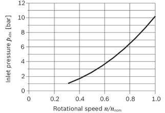
This diagram is only valid for the optimum viscosity range of vopt = 16 to 36 mm2/s
Please contact us if these conditions cannot be satisfied.
Pressure definition

| 1) | Total operating period = t1 + t2 + ... + tn |
Rate of pressure change
Maximum differential pressure at the shaft seal, size 10 ... 200

Maximum differential pressure at the shaft seal, size 250 ... 1000

Note
- The service life of the shaft seal is influenced by the speed of the axial piston unit and the case pressure.
- The service life decreases with an increase of the mean differential pressure between the case and the ambient pressure and with a higher frequency of pressure spikes.
- The case pressure must be equal to or higher than the ambient pressure.
Direction of flow
| Direction of rotation, viewed on drive shaft | |
| clockwise | counter-clockwise |
| A to B | B to A |
Permissible radial and axial forces of the drive shaft
| Size | 5 | 10 | 12 | 16 | 23 | 28 | 32 | 107 | 125 | 160 | 180 | 200 | 250 | 355 | 500 | 710 | 1000 | |||||||||
| Drive shaft | Code | B, C | Z, P | A, B | Z, P | A, B | A, B | Z, P | A, B | Z, P | A, B | A, B | Z, P | A, B | A, B | Z, P | A, B | A, B | A, B | Z, P | Z, P | Z, P | Z, P | Z, P | ||
| ⌀ | mm | 12 | 20 | 25 | 20 | 25 | 25 | 25 | 30 | 25 | 30 | 30 | 40 | 45 | 45 | 45 | 45 | 50 | 50 | 50 | 60 | 70 | 90 | 90 | ||
| Maximum radial force |
| Fq max | kN | 1.6 | 3 | 3.2 | 3 | 3.2 | 3.2 | 5.7 | 5.4 | 5.7 | 5.4 | 5.4 | 13.6 | 14.1 | 14.1 | 18.1 | 18.3 | 18.3 | 20.3 | 1.2 1) | 1.5 1) | 1.9 1) | 3 1) | 2.6 1) |
| a | mm | 12 | 16 | 16 | 16 | 16 | 16 | 16 | 16 | 16 | 16 | 16 | 20 | 20 | 20 | 25 | 25 | 25 | 25 | 41 | 52.5 | 52.5 | 67.5 | 67.5 | ||
| Permitted torque at Fq max | Tq max | Nm | 24.7 | 66 | 66 | 76 | 76 | 102 | 146 | 146 | 179 | 179 | 204 | 679 | 679 | 796 | 1021 | 1021 | 1146 | 1273 | ||||||
| Permitted differential pressure at Fq max | Δpq max | bar | 315 | 400 | 400 | 400 | 400 | 400 | 400 | 400 | 400 | 400 | 400 | 400 | 400 | 400 | 400 | 400 | 400 | 400 | ||||||
| Maximum axial force, when standstill or in non-pressurized conditions |
| + Fax max | N | 0 | 0 | 0 | 0 | 0 | 0 | 0 | 0 | 0 | 0 | 0 | 0 | 0 | 0 | 0 | 0 | 0 | 0 | 0 | 0 | 0 | 0 | 0 |
| - Fax max | N | 180 | 320 | 320 | 320 | 320 | 320 | 500 | 500 | 500 | 500 | 500 | 1250 | 1250 | 1250 | 1600 | 1600 | 1600 | 1600 | 2000 | 2500 | 3000 | 4400 | 4400 | ||
| Maximum axial force, per bar operating pressure | + Fax max | N/bar | 1.5 | 3 | 3 | 3 | 3 | 3 | 5.2 | 5.2 | 5.2 | 5.2 | 5.2 | 12.9 | 12.9 | 12.9 | 16.7 | 16.7 | 16.7 | 5.2 | ||||||


| 1) | When at a standstill or when axial piston unit operating in non-pressurized conditions. Higher forces are permissible when under pressure, please contact us. |
General notes
- The values given are maximum values and do not apply to continuous operation.
- The axial force in direction -Fax is to be avoided as the lifetime of the bearing is reduced.
- Special requirements apply in the case of belt drives. Please contact us.
Notes for sizes 250 ... 1000:
- In case of radial forces limited performance data is valid. Please contact us.
- In case of axial forces during operation of the unit please contact us.
Effect of radial force Fq on the service life of bearings
By selecting a suitable direction of radial force Fq the load on the bearings caused by the internal rotary group forces can be reduced, thus optimizing the service life of the bearings. Recommended position of mating gear is dependent on direction of rotation. Examples:
Toothed gear drive, size 5 … 180

Toothed gear drive, size 200 … 1000

| 1 | Direction of rotation "counter-clockwise", pressure at port B |
| 2 | Direction of rotation "clockwise", pressure at port A |
| 3 | Direction of rotation "bidirectional" |
Long-life bearing
Size 250 to 1000
For long life cycle and use with HF hydraulic fluids. Identical external dimensions as design with standard bearing. Subsequent modification to long-life bearing is possible. Bearing and housing flushing via connection U is recommended.
Bearing flushing
Flushing flow (recommended)
| Size | 250 | 355 | 500 | 710 | 1000 | |
| Flushing flow qv | l/min | 10 | 16 | 16 | 16 | 16 |